
Camera Basics
Introduction
The camera is the conduit for
your imagination to a final image. When creating your render you need
to decide what it will be used for, what its destination will be. Will
it be an image for film or broadcast, print or computer screen?
Whatever you image's destination, there
are two defining characteristics for it. One is how big it is, the other
is the shape of the pixels that make it up.
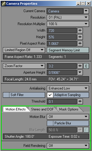
You can
make all these decisions in the Camera
Properties
window, which will appear when you pick a camera and hit the p button
on your keyboard, or the properties button on your LightWave screen.
Multiple Cameras
You can have as many cameras as you like in a scene (well, there's a standard limit at 100, but you can increase this in the LW8.CFG config file to an absolute maximum of 32,000). However, you can only render the current camera view. You add extra cameras into the scene by clicking on the Items > Add > Camera button, or you can clone existing ones (with Ctrl c). If you have more than one camera in a scene, you can choose the camera you wish to be active, when in Camera mode, either in the Camera Properties panel or the Current Item button under the main Layout window.
CameraSelector
This Master plug-in allows you to switch between different cameras in Layout. The current camera is still the one that gets rendered but this can be used to preview camera switches in-scene or in a Preview.
To access the CameraSelector, click on the Master Plug-ins button in the Utilities tab. This will bring up a window with a drop-down menu in which you can select CameraSelector. Double clicking on its entry in the Master Plug-ins list window will open the CameraSelector plug-in's window. To create a list of camera changes all you need do is scrub through your scene selecting the camera you want for each shot. Simply click on the Add button in the CameraSelector window for each camera change you wish to take place. If you then start playing your scene you will see that the camera switches at the time you stated. If you wish to remove a camera change, just select the change you want to get rid of and hit delete in the CameraSelector window.
If you would like to see your scene play through just one camera view, you can turn off Camera Selector by clicking the Enable Dynamic Preview switch, during scene playback if you wish.
For CameraSelector to work its magic, it needs information not normally available to master plug-ins so it automatically creates a null object called "SpecialTriggerNull" whose only purpose in life is to serve CameraSelector. If you wish to use a different object you can select it on the Trigger drop-down menu but, normally, there is no reason to do so.
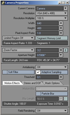
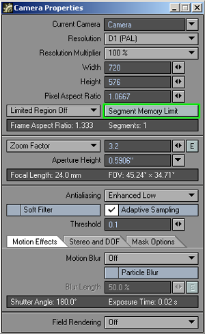
Resolution
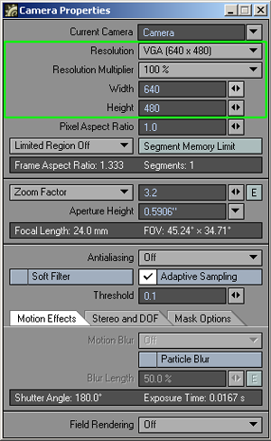
The Resolution Preset
drop-down menu will present you with a series of pre-defined resolutions
to choose from for your render. It will automatically set the Width, Height
and Pixel Aspect ratio fields.
Note: You can add your own presets to this list, but it requires you to delve into the LW8.cfg file. If this thought doesn't scare you, then we'll proceed.
If you look in your LW8.cfg file you see that near the top there are several lines that look like this:
ResolutionPreset 1920 1080 1 0 0 1920 1080 HDTV (1920 x 1080)
The first two numbers are the size of the frame, the next one is the pixel aspect ratio and then the next four are the default Limited Region frame. The last bit of text is the title of the preset that will appear in the drop-down menu.
Feel free to make your own lines. For instance here's one you may wish to add to get the ball rolling:
ResolutionPreset 2480 3508 1 0 0 2480 3508 A4 page (300dpi)
As you can tell from the title, this Resolution Preset gives you a full A4 page at 300dpi.
The width and height fields can be set to anything between 16 and 16,000 pixels. Be aware that larger resolutions can make serious demands on the memory of your machine.
The Resolution Multiplier gives you a much more consistent way of quickly checking a scene rather than changing the width and height fields when you want a small test render. It takes into account the scaling of things such as particle, line, and edge thickness, as well as the glow radius.
If you have selected a resolution preset and you alter the width or height fields, it will override any preset and the menu will then show the word Custom. If you have already set a resolution multiplier it will then operate on the width and height settings you have chosen.
The resolution multiplier does not scale an image after it has been rendered so it can be used in a situation where the boss asks for an image about "two thirds as large again". Deciding a resolution to use on a project is largely down to its intended use. An image for broadcast can almost always use the appropriate PAL or NTSC resolution presets. An image for print will always vary depending on the size of the final image, whereas film is usually one or two size settings. Both provide high-resolution images that can take a long time to render and a lot of memory. If, however, you are rendering an animation for display on a computer, you will often want to use a lower resolution for reasons including the running speed of the final animation and its file size.
Print Assistant
In the Additional
menu in the Utilities tab, you
should find the Print Assistant
plug-in. This will enter width and height details for your render based
on inch or Pica measurements at a specified dpi rate.
Note: You can also enter print sizes directly into the width and height fields using LightWave's ability to do maths in these fields. For instance, the seemingly complicated sum: 8.26*300 gives the width of an A4 page in inches at 300dpi. If you would rather work in metric, the width of an A4 page is 21 cm, so: 21*300/2.54 will give you roughly the same result (the /2.54 converts the sum into inches). The centimetre value is more precise since an A4 page's size is worked out based on metric rather than imperial measurements.
Pixel Aspect Ratio
Once you've
been using a computer for a while you forget that pixels actually come
in different shapes. Ones for NTSC TV are tall and thin; ones for PAL
TV tend to be a bit fatter, while ones for print are the same as those
for computer screens – square as square can be.
![]() The
Pixel Aspect
ratio setting in LightWave is calculated by dividing the width of a pixel
by its height. A pixel intended for print or a computer screen is square,
as we said, so its aspect ratio is 1.0. Because NTSC pixels are taller
than they are wide, the aspect ratio tends to be between 0.86 and 0.9.
PAL ones, on the other hand, tend to vary between 1.01 and 1.06. Values
for widescreen displays are considerably wider in both NTSC and PAL.
The
Pixel Aspect
ratio setting in LightWave is calculated by dividing the width of a pixel
by its height. A pixel intended for print or a computer screen is square,
as we said, so its aspect ratio is 1.0. Because NTSC pixels are taller
than they are wide, the aspect ratio tends to be between 0.86 and 0.9.
PAL ones, on the other hand, tend to vary between 1.01 and 1.06. Values
for widescreen displays are considerably wider in both NTSC and PAL.
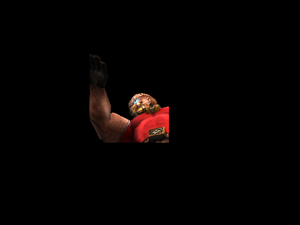
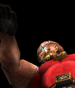
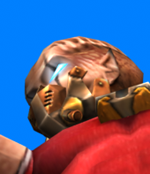
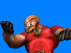
Why worry about the pixel aspect ratio? After all a pixel is a pixel, right? Well yes, but if you look at a perfectly round ball that has a radius of 50cm and you are using an NTSC resolution preset, the ball will look squished on a computer monitor, whereas it will look perfectly round on your NTSC monitor. When selecting one of the resolution presets you will notice that the pixel aspect ratio changes along with the resolutions for width and height. As for things looking squashed or stretched on your computer monitor, I'm afraid it's either something you'll have to get used to, or you will need an output to a proper broadcast monitor to reassure yourself.
![]()
![]()
![]()
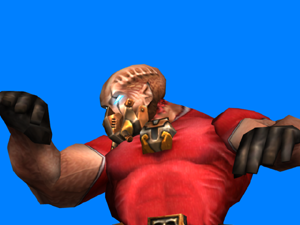
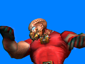
Same ball,
different monitors. Left: NTSC (0.9) Middle: Computer monitor (1.0) Right:
PAL (1.0667)
Frame Aspect Ratio
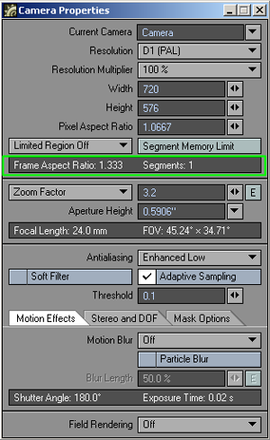
Before we move on, don't confuse the
pixel aspect ratio with the
frame aspect ratio figure, often
referred to simply as the aspect ratio. The way to work this out is to
take the pixel width of a picture, divide it by the pixel height and multiply
the result by the pixel aspect ratio. As an example, a standard VGA screen
is 640 x 480. This equates to a frame aspect ratio of 1.333, worked out
by doing the following sum (640/480)*1 and converting it to a ratio. You
will often see this figure quoted on the back of DVD cases to indicate
the width of the display compared to its height (how much of your TV screen
will be covered by black bars in other words).
Lens Settings
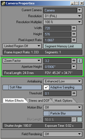
The zoom
factor drop-down menu allows you to set a zoom factor equivalent to a
real world camera lens. It has four different types of zoom factor for
you to choose between and LightWave defaults to a zoom factor of 3.2,
equal to a 24 mm lens. LightWave users that are familiar with real world
camera equipment may find using the Lens Focal Length type on the drop-down
menu easiest to use. Those who are solely used to LightWave's way of doing
things may be more comfortable using the Zoom Factor type. You can also
use the Horizontal and Vertical FOV (Field of View) settings. These set
the degree of angle of view.
Left:138
mm lens, Right: 8 mm lens
Smaller
Zoom Factor or Lens Focal Length values will produce a wider angle lens
effect while larger values give a narrow field of view, similar to a telephoto
lens effect. You can create an envelope to achieve effects such as reverse
zooms where you pull the camera away while concentrating the field of
view. The envelope will be based on Zoom Factor regardless of which mode
on the drop-down you choose to use.
Aperture
Height
You can change the aperture height of your virtual camera in LightWave
to match the optical characteristics of a real world camera, especially
for film work. Changing this setting will only affect the Depth of Field
effect and the lens focal length.
Note: Aperture Height is always listed in inches, even if you are using a metric unit system.
Camera
Settings in a Viewport
When you use the camera view (numeric keypad 6), areas of the viewport
that are outside the render area will be coloured with the overlay colour
chosen in Display Options (d).
You can have horizontal bars showing the exclusion or they can be vertical
bars, depending on the frame aspect of the render you are making.
Furthermore you will be able to show safe areas for overscan and underscan
displays by turning on the Show
Safe Areas
switch in the Display Options (d), and also
have a grid displayed to allow you to divide up the frame better by selecting
Show Field Chart.
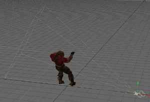
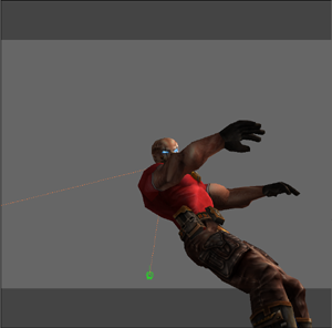
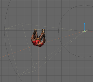
If you are
using a view other than the camera view, you will see the camera represented
on-screen together with a pyramid showing its field of view. This pyramid
is only shown when the camera is the selected item.
 If
you are using an orthogonal projection and you have Show Fog Circles
option switched on in the Display
Options
(d) you will be able to see the area around the camera affected by fog.
If you press Ctrl F6 and choose a standard fog type while in a top view
mode, for example, you will be able to see circles around the camera indicating
a minimum and maximum fog radius around the camera.
If
you are using an orthogonal projection and you have Show Fog Circles
option switched on in the Display
Options
(d) you will be able to see the area around the camera affected by fog.
If you press Ctrl F6 and choose a standard fog type while in a top view
mode, for example, you will be able to see circles around the camera indicating
a minimum and maximum fog radius around the camera.
Left: What
Layout looks like, Middle: Render Limited Region Borders, Right: Render
Limited Region No Borders
There are two different types of limited region that you can use, either with or without borders and you cycle through these choices by repeatedly hitting the l key or by choosing the drop-down menu in the Camera Properties window. The difference between a limited region with a border and one without is the fact that a limited region with a border puts your limited region on a black page the size of a full render, whereas a limited region without borders will just render the shape you desire as the full image. The frame aspect ratio in Camera Properties will remain at the aspect ratio for a full frame, but all other options, such as anti-aliasing and Masks still apply.
Memory
Considerations
Limited Region allocates only enough memory to render the horizontal limited
region area. If you stitch parts of an image together, you can effectively
render images that are much larger than those you could render one pass.
This is especially useful for high-resolution print images or in low memory
situations. However, note that some post-processing filters require a
full-sized image. In such cases, you may be able to apply those filters
to the "stitched" image in an additional step. The way to do
this is to take your final rendered image and save it to disk. Then clear
your scene – better yet, quit and restart LightWave – and load this image
into an empty scene. Make it the camera backdrop and add whichever post-process
filter you wish to use, and then render again. Because of the fact that
you aren't rendering all the objects, textures, image maps, etc. the memory
requirements will be a lot lower.
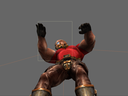
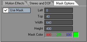
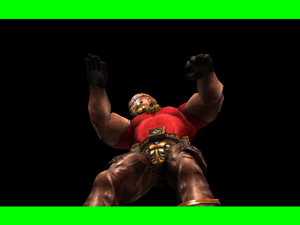
Masking
out a region
Using a mask is a little like rendering a limited region, but allows you
to define a colour for the area outside the region you define. Set the
Mask Options in the Camera
Properties window. Click on the Use
Mask button to open up the settings for use. The figures you enter
dictate the render area; everything outside it will be the colour you
choose. You can use this feature to get a letterbox-style effect.
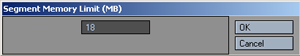
Segment memory limit
When rendering
an image you can dictate the amount of memory that LightWave should devote
to rendering – this is apart from whatever memory LightWave uses for shadow
maps, image mip-mapping or geometry memory costs. The default value for
Segment Memory Limit is 8 MB, but changing it will result in a question
of whether the new value should be set as the default. A value of 18MB
is enough to render a full frame at video resolution (either NTSC or PAL)
in a single segment. Setting it higher than this will not result in LightWave
devoting more memory to render the image, the limit is just that. If additional
memory is assigned and not needed it will not be used. The Segment Memory
Limit can be set as low as 1 MB, useful for rendering scenes with particularly
stringent memory requirements.
There are other reasons for setting a memory limit to be enough to render
a frame in a single segment. The first is that an image rendered in a
single segment renders faster than one with multiple segments. The second
is the fact that some image filters require an image rendered in a single
segment, otherwise unsightly borders can occur, for instance where blurring
occurs right up against the edge of a part of an image that becomes visible
when the image is assembled.
NOTE: On platforms that support virtual memory, you may get better results using smaller segments that fit within available RAM. (Using one segment that may not fit entirely in RAM forces you to page to the hard disk and slow down rendering). You may need to experiment with segment values to find a useful setting.
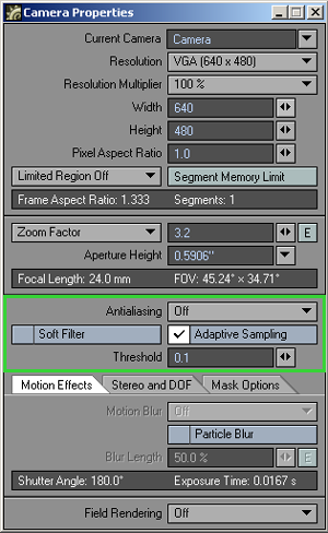
Anti-aliasing
If aliasing, the stepping effect on diagonal lines seen when image resolution
isn't high enough, is the crime; then anti-aliasing is the cure. Aliasing occurs because a pixel is rectangular
in shape and this means that there will always be a jagged effect with
anything other than rectangular shapes. This effect can be reduced by
working at high resolutions but cannot be removed. All image-processing
programs, including LightWave, employ a device called anti-aliasing
in order to reduce this stair-stepping effect. It compares the RGB values
of two neighbouring edge pixels and adds an average-valued pixel between
them. This fools the eye into seeing a smooth line.
LightWave
has five levels of anti-aliasing from None to Extreme.
These levels are then subdivided into two: normal and enhanced anti-aliasing.
Enhanced will usually give a better effect for a given level of anti-aliasing
because it uses almost twice as many samples for each pixel and filters
them more intelligently, giving a better result at an additional cost
in rendering time.

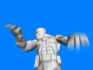
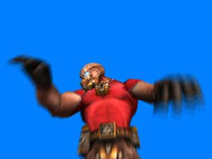
Left: No
antialiasing Right: Enhanced Medium antialiasing
Low or medium levels of anti-aliasing usually suffice for video resolution images, but if depth of field or motion blur is required in a render, the high level of anti-aliasing may be useful. The extreme level of anti-aliasing is useful for the highest level of fidelity in motion blur or depth of field.
Anti-aliasing can also be achieved by rendering at a higher resolution than needed, with no anti-aliasing, and then shrinking the resulting image using another graphics package or LightWave itself. To use LightWave for this, simply load the rendered image into an empty scene and set the render resolution to less than the image's original resolution. You do not need to turn on anti-aliasing. Now render at the final desired resolution – something that will take place very quickly – and you will have your anti-aliased image.
Depth
Buffer Antialiasing
The Depth Buffer Antialiasing command (Effects command group) has been
added to specify how the Z-buffer values from multiple antialiasing passes
should be combined when creating a final depth buffer for output. Executing
the command will display a small dialog. The Minimum Value setting (the
standard behavior) causes each pixel to store the closest of the depths
found at that pixel in all passes. The Average Value setting causes each
pixel to store the average of the pixel's depths in all passes. The Depth
Buffer Antialiasing setting is not saved with the scene, so you will need
to enable it each time you set up a render. This also means that it cannot
be used with a network render.
Antialiasing
Using Edge Detection
By default, LightWave uses Adaptive Sampling (edge detection) to determine
which areas of an image should be antialiased. This focuses the antialiasing
process primarily on the edges of objects. With Adaptive
Sampling active, you can tell LightWave which areas to antialias
by entering a sampling Threshold
value. If the Adaptive Sampling
option is inactive, LightWave will antialias the entire frame.
The adaptive sampling Threshold functions by comparing the brightness of two neighboring pixels. A value of 0 will antialias everything in the scene, but values between .0314 and .1255 work well in most situations—the higher the level, the fewer edges are detected and, thus, the lower the rendering time.
A value of 1 is the maximum brightness difference in a 24-bit color space; however, internally LightWave can work with pixels brighter than RGB 255, 255, 255. Since you might want antialiasing only when nearby pixels differ by more than 1, the adaptive sampling Threshold can be set higher than 1. If you want to ensure that extra antialiasing is never performed, use a large Threshold value.
When Adaptive Sampling and the Show Rendering in Progress (Render Options panel) options are active, you can see the area where LightWave has detected edges highlighted in white on the rendering screen. By adjusting the sampling Threshold, you can increase or decrease the amount of white areas (and thus the antialiasing) to correspond to areas you know contain prominent edges. These white lines do not appear if you are using one of the enhanced anti-aliasing modes.
HINT: When you turn off Adaptive Sampling, images take longer to render, but you will achieve better antialiasing results. If using Adaptive Sampling does not give you the results you wish or fine lines are being missed (even at a low or zero sampling Threshold level), disable Adaptive Sampling.
Soft
filter
In the Camera Properties window under the antialiasing level drop-down
menu you will see an option for a soft filter. Selecting this will render
your objects with a soft look, akin to a film image. It is not an appropriate
substitute for anti-aliasing except in real emergencies. It also only
affects objects, background images will not be affected.
Motion Blur Effects
When using a camera to film fast-moving objects these objects are often
blurry. This is because they continue moving while the shutter of the
camera is open and it is this feature that LightWave aims to replicate
with Motion Blur.
Motion Blur becomes essential when animating, especially for use with live action. It prevents the crisp quality that normally pervades computer-generated animation and helps an animation appear more fluid.
LightWave's motion blur system takes everything that can change over time
into account. From shadows, to surfaces, from light intensities to object
or camera movement. It accounts for curved motion and does not blur in
a linear fashion, but rather following the path the motion is taking.
For motion blur to work, you have to have some level of anti-aliasing enabled. LightWave uses these anti-aliasing passes to generate the additional images used by motion blur. You will be able to see the process working if you have a render view while rendering. For each anti-aliasing pass, LightWave seems to move the objects a little and then composites them all together to get the motion blurred image. Because only five steps (a low level of anti-aliasing) can give a stepped effect, higher levels of anti-aliasing are recommended. There are two types of motion blur - normal and dithered. Dithered provides a better quality result with double the number of images to dither in-between, and doesn't take as long as using the next level of anti-aliasing, but provides results just as good if not better.
HINT: Using Soft Filter in combination with Dithered Motion Blur creates an even better effect.
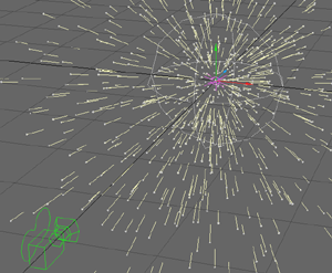

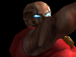
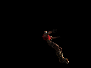
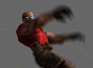
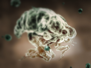
Left: a Particle
explosion Right:Rendered with Particle Blur on.
Stereoscopic rendering
Stereoscopic rendering gives you the
familiar two-image set seen from slightly different perspectives that
can be combined in a variety of ways to produce a 3D, 3D image. Further
explanation of stereoscopy is outside the remit of this document, but
there are plenty of resources on the web for people interested in this
field. F9 renders will not show
the two images that make up the stereogram, you will have to use the F10
render and save your images to be able
to get both sides of the perspective – the F9 render just gives you the
left eye. When rendering using the Stereoscopic rendering function you will get two images for each frame of
your animation suffixed with either an L or R for Left and Right eye images
respectively.
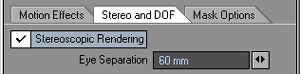
The Eye Separation
field is set by default to 60 mm – the average distance between the centres
of the pupils in a human adult. You can change this value to exaggerate
the 3D effect.
Note: Use the Anaglyph Stereo image filter
if you wish to make a 3D image viewed using red/blue glasses.
Depth of Field
LightWave is really clever. You can
have a whole series of objects in a scene at differing distances from
the camera and LightWave will render them all in perfect focus! The human
visual system can't even do that, and that's the problem. For your images
to look as realistic as possible, they need to use a feature of reality
called Depth of Field. Fortunately,
you can emulate this functionality inside LightWave. You need to render
an image with anti-aliasing set to more than Low for the effect to work
(or even be available), and then you can turn on Depth of Field. If this is going to give you unacceptably
long rendering times, please also check out the image filter Digital Confusion.
Depth of Field
refers to the area of acceptable sharpness in front of and behind the
actual area in focus. When you enable Depth of Field you can change two
settings. The first setting, Focal
Distance,
refers to the distance from the camera to the object that you would like
to be in focus.
The second option is Lens F-Stop. Camera focus typically encompasses a range, from near to far, that we call "in focus". Objects nearer than this, or farther than this, appear out of focus. The Lens F-Stop value determines the range of focus around the Focal Distance (the near and far distances from the camera in which objects still appear in focus).
If you are familiar with real world cameras, you know that the f-stop sets the diameter of the lens aperture. An f-stop of f/4 (which corresponds to a LightWave Lens F-Stop of 4) indicates an aperture diameter that is a quarter of the lens' focal length (LightWave’s Lens Focal Length). Higher f-stop numbers refer to a smaller aperture, because the number is the denominator of a fraction. The aperture (f-stop) control on a real camera affects both the brightness and sharpness of an image. In the LightWave world, the Lens F-Stop works in the context of Depth of Field where it affects only sharpness.
The larger the Lens F-Stop value, the larger the depth of field, that is, the greater the distance between the near and far distances where objects appear in focus. Conversely, the smaller the Lens F-Stop, the smaller the range of focused area.
In general, remember that the Depth of Field becomes progressively greater as the Lens F-Stop setting increases, the Focal Distance value increases and/or the Zoom Factor (and therefore the Lens Focal Length) setting becomes smaller.
When starting to experiment with Depth of Field, try using a short Focal Distance setting (shorter than the distance to the object you wish to be in focus) so the depth of field is more pronounced. You can also look at the scene in an orthogonal viewport and be able to see a ring around the camera indicating the focal distance of your lens – the distance at which things are in perfect focus. Don't worry that the display will get confused if you are also showing fog circles in the viewport; the lines indicating the fog are visibly different to that of the focal distance.
HINT: Rather than waiting for realistic renders
when setting up your depth of field, use the Quickshade rendering method
in the Rendering Options window to get a quick preview of how blurry or
sharp the objects are in your scene.
Left: Quickshade
render Right: Full render
HINT: You can get an accurate measure of the distance between the camera and your selected object using the Ruler or Range Finder custom objects.
You can also set a null to be parented to the camera and linked to the focal distance envelope of the camera so that you can control the focal distance by moving the null. This way you can get an interactive distance tool to control the focal range. Here's how you do it:
1. Add a null to your scene and parent it to your camera in the Motion Options window (m). In Layout, turn off the X and Y axes so that the null can only be moved along its Z-axis. Name this null "CameraFD";
2. Go to the Object Properties window (p) and assign the Range Finder custom object to the null. You can turn on the link to camera if you wish;
3. Go to the Camera Properties window. Turn on at least medium anti-aliasing to enable the depth of field function and make sure that the Focal Distance is set to 0 m;
4. Hit the Envelope button next to this field so that you can link the distance the null is away from the camera to the focal distance used.
5. Click on the Modifiers tab in this window and use the Channel Follower Modifier. Double click on this in the list under the Add Modifier drop-down menu to set up the Channel Follower modifier;
6. From the list of channels that appear choose the CameraFD.Position.Z channel, make sure that the time lag is set to 0, scale to 100% and start frame and end frame to 0 and –1 respectively.
7. You can now key the position of the null and the camera's focal range will be set to the distance the null is away from the camera meaning that you can pinpoint a single object in a busy scene to be focussed upon. The smaller the value for the Lens F-Stop, the smaller the range of focus.
